


SNASA | Design by Nature
The Challenge | Design by Nature
RoACH - Rover Analyzer of Collision Holes
Automated crawling rover to check the outside surface of a spacecraft for meteoric damage.
WEBSITE
OBJECTIVES
Challenge: Design by Nature.
Develop an autonomous device able to scan the exterior of a spacecraft and detect damage from micrometeorites and space debris.
CONCEPT
This project sets the guidelines to develop a self-operating rover able to spot any holes in the external coating of the vehicle. Techniques to determine position, dimension, depth and penetration angle have also been developed. Both appearance and movement have been inspired by those of insects.
MATERIALS
The main aspect to take into consideration for the choice of the materials is the wide range of temperatures that the rover should be able to withstand. For reference, the temperatures have been considered similar to those registered on the ISS (International Space Station), reaching as low as -250°F and as high as 250°F.
Structural components are intended to be built in aluminum 2219-T6, an alloy containing aluminum, copper and manganese, which has a fusion temperature of 1009°F. In fact, it is already widely used on device meant to operate in outer space because of its reduced weight and lower cost relative to titanium.
The natural choice for the thermal insulation is aluminized mylar, a metalized polymer common as a highly-reflective coating to dissipate the incoming solar radiation. Since the layers are as thin as 6μm, mylar can be put on top of Kapton and covered with beta-cloth. Kapton is a polyimide stable between -452°F and 752°F. Beta-cloth is a woven silica fiber mixed with Teflon that keeps the lower layers from erosion.
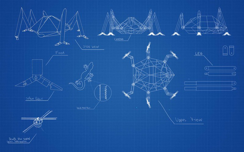
DISPLACEMENT
The rover has six legs, each consisting of two segments ending with a gripping paw. The junction between the main body and the first segment consists of to sections that allow the arm to rotate freely around the “shoulder”. The second segment is pivoted to the first, allowing the arm to fully extend. The last junction, between the paw and the second segment, is like the first one to allow a perfect adherence to the surface.
In order to allow the rover to overcome obstacles larger than itself, the second segment has been designed as telescopic by inserting a smaller cylinder within. However, this kind of setup would make it impossible to properly cover the inner cylinder with the insulating material. Therefore, it should only be used when strictly necessary and for the shortest timespan possible.
The motion is made particularly stable by imitating the “alternated tripodal” movement of insects, derived from multiple studies on actual insects. This consists in keeping the front and back leg of one side and the middle one of the other side on the ground while the other three move.
Paws
A key element in the development of this project has been the development of a mechanism to stick to the surface without damaging it. Using the ISS as reference, the surface has been considered to be mainly covered in polymeric materials, which wouldn’t allow to stick to the surface using magnetic feet. The only feasible alternative found is the use of synthetic setae. These are a high-tech material that imitates the micrometric spatulae found on the paws of geckos, allowing them to stick to almost any surface.
The main contribution to this phenomenon is from the Van Der Waals forces and, to a lesser extent, from capillary forces when certain surfaces are involved. Since the forces in action are due to the interaction of induced dipoles, they can act on an extremely wide range of materials, even in the vacuum of space.
Of great interest is the high resistance to shear stress of this material, amounting to about 50 𝑁𝑐𝑚2 , while it only opposes to peel forces with 1.2 𝑁𝑐𝑚 . Moreover, some studies claim that these properties remain nigh unaltered between -238°F and 932°F.
The paw consists of a main cylinder, containing a pivot to which to lesser arms are connected. These are kept at a predetermined angle by two spiral springs and are hollow. In the cavity there is a solenoid that attracts or repels a permanent magnet located on the far side and mounted on two rails. The magnet is then the only component directly connected to the external foot.
The lower surface of the foot is covered in synthetic setae. The paw has therefore two identical feet that are pulled toward the center when the paw is pressed against the surface, thus firmly sticking to it by means of the shear forces produced.
POSITION AND MOVEMENT SENSORS
Similarly to insects, the system in charge of analyse the immediate surroundings is placed mainly in the front antenna. In the shaft is located an antenna to locate the rover relative to the vehicle, while in the sphere at the top of it there is a system meant to survey the environment for obstacles.
To locate the rover, the antenna must be able to receive and emit in the EHF radio frequency, such as in the W-band. This should allow, after appropriately locating beacons on the spacecraft, to triangulate the position of the rover within a few centimeters.
Obstacle detection and the adjustments necessary to avoid them are a much more complex issue. A possible solution is to deploy a LiDAR sensor operating in the near or, even better, far infrared. This would avoid the any laser emission in the visible range. The technology is already largely available, commonly used for geomapping and as a safety measure on self-driving cars. The mechanism is quite complex but it consists essentially in the emission of laser pulses, possibly with different wavelengths, to build a 3D module of the surrounding area. Moreover, techniques to separate the LiDAR pulses from environmental disturbances have already been developed.
MAIN BODY
The main body should measure about 60x40x30cm and have a polygonal shape. On the lower front side is located a downward-facing camera, on the back there are solar panels, on the sides the pivoting points of the legs and the bottom must be plain to maneuver more easily a rangefinder.
On the inside there should also be a computer to analyze the collected data, a Li-ion battery and an antenna to broadcast the results to the crew inside the surface.
Camera
It should be placed upfront and able to see the ground right in front of the rover. To protect the lens from direct sunlight, a lens hood must be added as well as a flashlight to be able to record images when the surface isn’t naturally lit.
The camera sends the images to an AI trained to recognize holes in the ground. The AI is even capable of estimate the probability of a correct detection. The image is also divided into sub-images as to determine more precisely where the hole is and restrict the area that the telemeter should then further inspect.
Laser telemeter
The laser telemeter is used to determine the size, penetration angle and depth of the hole. It is located in the lower half of the rover and it is mounted on two orthogonal rails (such as those of 3D printers). Between the telemeter and the rails there are a rotating cylinder and a bending arm, thus allowing the telemeter to span over the whole surface underneath at any chosen angle.
The following process has been developed in the assumption that within the hole there is a direction of maximum inclination along which lie all the lower points. Said assumption was beforehand proven mathematically through the parametrization of a surface connected to a cylindrical sloped hole.
The parameters are measured following these steps:
- The telemeter cross-measures the area highlighted by the camera.
- The measured heights will have a discontinuity is there actually is a hole.
- The area is split in a grid and the height evaluated at each node. This process is repeated making the grid ever more precise until the lowest point is detected with a pre-selected precision.
- From the lowest point found, the direction of maximum slope is found by surveying the immediate surroundings with the laser.
- Sampling along this direction it’s possible to determine 𝛼=𝑎𝑡𝑎𝑛(𝑧1−𝑧2𝑥).
- Likewise, the points 3 and 4 can be found. The former when there is a discontinuity in the measured height and the latter when the slope is no longer the same.
- From the slope m43, 𝜗=𝑎𝑡𝑎𝑛(𝑚43) can be found.
- The penetration angle is then 𝛾=𝛼+𝜗.
- The telemeter is places as to send the laser into the hole with and angle α relative to the base of the rover. This guarantees the laser to reach the bottom of the hole and measure the depth.
BIBLIOGRAPHY

SpaceApps is a NASA incubator innovation program.