


Robocon Team | Make Sense Out of Mars
Awards & Nominations
Robocon Team has received the following awards and nominations. Way to go!
The Challenge | Make Sense Out of Mars
upheaval robocon
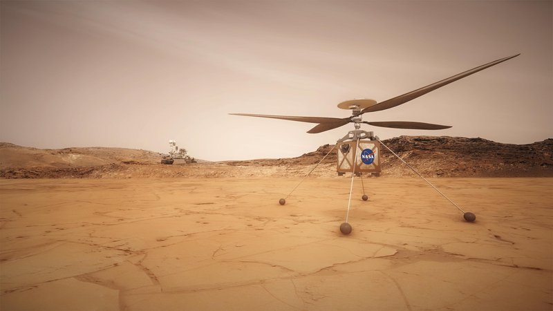
Mars scout helicopter
Abstract:
The Mars Helicopter Scout (MHS) is a planned robotic helicopter expected to help scout interesting targets for study on Mars, and plan the best driving route for Mars rovers. It is a technology demonstrator that will form the foundation on which more capable helicopters can be developed for aerial exploration of Mars and other planetary targets with atmosphere.
Introduction:
The Mars Helicopter, a small, autonomous rotorcraft, to demonstrate the viability and potential of heavier-than-air vehicles on the Red Planet. Mars have such a rough environment and a really thin atmosphere (1% of the density of earth’s atmosphere), low gravity ( earth’s gravity) and a cold weather (-140 ℃ to 30 ℃), so because of that it was hard to make it fly in these conditions, the scout helicopter will get to space with a rover side-by-side in the same rocket chamber, Actual Mars atmosphere conditions are significantly colder (e.g. approx-50C), resulting in different blade aerodynamics conditions such as the Mach number. However, since the helicopter is operated with conservative tip Mach speeds (≤ 0.6), flight dynamics and performance results at ambient temperatures (e.g. approx. 20 C) which can be easily matched to the Mars conditions. A various force/torque sensors in the chamber, a Vicon motion tracking system, stroboscopic lighting, a thermal camera, and temperature sensor monitors were developed to support operation, the main objective of the helicopter that it would fly ahead of the rover almost every day, checking out various possible points of interest and helping engineers back on Earth plan the best driving route, Scientists could also use the helicopter images to look for features for the rover to study in further detail. Another part of the helicopter's job would be to check out the best places for the rover to collect key samples and rocks for a cache, which a next-generation rover could pick up later.
Literature review:
Components of the scout helicopter:
1-Rotor:
The rotor system provides lift for the helicopter as well as forces required for the directional control of its trajectory. The design uses a1.21 m diameter co-axial counter-rotating rotors with a rigid rotor i.e. no flap or lag hinges. The rotor is very stiff with a very high flap frequency (better than 1.9/rev) so as to lower some of the control challenges identified earlier. There are swash plates on both the upper and lower rotor, each with collective and cyclic control. The maximum rotation rate for the rotors is 2800 rpm. The rotor is fabricated from carbon fiber composites for most of the primary structure. The blades use a low Reynolds number airfoil with optimized twist and chord. Seals around bearings and a soft boot around the swash plate assembly mitigate against dust in the Mars atmosphere. Actuator power electronics are co-located with each actuator, and the motors self-heat before flight. The rotors are actuated with a custom 46 pole brushless motor with solenoid wound teeth using rectangular copper wire. Three Maxon brushed DC motors (DCX10) operating through a 4-stage gear-box control the height and tilt of each swash plate. Chinese weights provide a restoring force on the blade moments when under centrifugal loads thereby reducing the torque requirements on the swash plate actuator
2-structure
The helicopter is built around a central mast - a hollow structural tube that runs from the top of the helicopter to the bottom. Within this tube are the wires from the Electronics Core Module (ECM) to the propulsion motor and servo elements, as well as to the host spacecraft. The mast tube is designed to be stiff so as to minimize control interactions, as well as have low thermal conductivity to minimize thermal leakage into the ECM. Attached to the mast are (ordered from top to bottom):
• Upper Launch Lock. This attaches the helicopter to the host spacecraft prior to deployment onto the surface. Attached to the launch lock are deployment devices, wires to provide power and communications prior to deployment, and separation connectors to cleanly disconnect electrical lines upon deployment.
• Solar Panel. The solar panel substrate is attached to the mast and the cells are mounted onto this substrate.
• Upper & Lower Rotors. The rotor hubs are attached to the mast and include the various non-rotating elements such as the servos, the non-rotating portion of the swash plate, the rotor windings, and the rotor power electronics.
• Landing Gear Mounting Plate. This consists of a plate to which is connected 4 light-weight legs.
• Fuselage Warm Electronics Box. The fuselage consists of a very lightweight structural frame to hold the thermal skin of the helicopter, and the 30 mm gap insulation between the skin and the ECM.
• ECM Assembly. The ECM is mounted onto the mast and consists of the battery, the Battery Interface Board (BIB), and electronics circuit’s board for the avionics.
• Upper Sensor Assembly. This consists of an inclinometer, IMU and associated vibration isolation elements mounted on the mast as close to the center-of-mass of the vehicle (to minimize the effects of angular rates and accelerations). The Lower Sensor Assembly (consisting of an altimeter, cameras and a secondary IMU) is mounted directly onto the ECM and not onto the mast.
• Lower Launch Lock. This holds the helicopter to the host spacecraft on the other end prior to deployment.
3- Avionics Computing
A three-level fault-tolerant computing architecture is used on the helicopter. Software is implemented using the F’ software framework .The avionics design is required to have low mass, low power and adequate radiation tolerance. A set of candidate parts to meet these requirements have been incorporated into the design which is now described.
4- Sensors
On-board sensors are used for vehicle control during all phases of flight. Data from IMU’s, an altimeter, and navigation camera image derived velocimetry is used to produce a navigation solution consisting of helicopter position, velocity, attitude, and other auxiliary variables. An inclinometer is used on the ground prior to flight to calibrate the IMU accelerometers biases. The helicopter also carries a color camera to provide images of terrain and other features for return to Earth.
The sensors used are Commercial-Off-The-Shelf (COTS) products. The candidate set of parts include:
• IMU: These are two 3-axis MEMS device from Bosch (Sensortec BMI-160), one for the upper sensor assembly in a vibration isolation mount, and one on the lower sensor assembly where it is co-located with the cameras.
• Inclinometer: This is a 2-axis MEMS MuRata device (SCA100T-D02)
• Altimeter. This is a time-of-flight altimeter with a range of 10’s of meters from Garmin (Lidar-Lite-V3). • Navigation (NAV) Camera. This is a global-shutter, nadir pointed grayscale 640 by 480 pixel sensor (Omnivision 13 Downloaded by NASA AMES RESEARCH CENTER on January 8, 2018 | http://arc.aiaa.org | DOI: 10.2514/6.2018-0023 OV7251) mounted to a Sunny optics module. It has a field-of-view (FOV) of 133 deg (horizontal) by 100 deg (vertical) with an average Instantaneous Field-of-view (IFOV) of 3.6 mRad/pixel, and is capable of acquiring images at 10 frames/sec. Visual features are extracted from the images and tracked from frame to frame to provide a velocity estimate.
• Return-to-Earth (RTE) Camera. This is a rolling shutter, high-resolution 4208 by 3120 pixel sensor (Sony IMX 214) with a Bayer color filter array mated with an O-film optics module. This camera has a FOV of 47 deg (horizontal) by 47 deg (vertical) with an average IFOV of 0.26 mRad/pixel.
5- Landing System
The landing system consists of 4 legs made of tapered carbon fiber/epoxy tubes. The feet are designed to prevent the leg from digging into soft landing surfaces. They also provide some damping by scrubbing against the ground as the leg flexes. Additional energy absorption is provided by flexible deforming elements at the hinges connecting the legs to the landing gear mounting plate which is affixed to the mast. The leg designs are tested against a variety of Martian surfaces ranging from hard rock to deep sand. The landing system provides for a passive drop onto the ground from a height of 0.3 m with only limited attitude rate control active during the final contact event with the ground. This minimizes ground-control interactions that could de-stabilize the helicopter. The landing gear is designed to allow the landing on surface with slopes up to 10 deg in any direction with the vehicle at an additional roll (or pitch) angle of 30 deg. Vertical velocity at the height where the passive gravity drop is initiated can be as high as 2.5 m/s. A horizontal velocity of up to 0.5 m/s can be present due to delivery errors in the control system.
6-Telecommunication system:
Once the viechel separated from the rover it can only communicate or be commanded from earth only. This link is implemented using a COTS 802.15.4 (Zig-Bee) standard 900 MHz chipset, SiFlex 02, originally manufactured by LS Research. . Two identical SiFlex parts are used, one of which is an integral part of a base station mounted on the host spacecraft, the other being included in the helicopter electronics. These radios are mounted on identical, custom PC boards which provide mechanical support, power, heat distribution, and other necessary infrastructure. The boards on each side of the link are connected to their respective custom antennas. The helicopter antenna is a loaded quarter wave monopole positioned near the center of the solar panel (which also serves as ground plane) at the top of the entire helicopter assembly and is fed through a miniature coaxial cable routed through the mast to the electronics below. The radio is configured and exchanges data with the helicopter and base station system computers via UART.
7- Power & Energy System
The helicopter is powered by a Li-Ion battery system that is recharged daily by a solar panel. The energy in the battery is used for operating heaters to survive the cold Martian nights as well as operate the helicopter actuators and avionics during short flights lasting from 90 seconds to a few minutes. Depending on the latitude of operations and the Martian season, recharging of this battery through the solar panel could occur over one to multiple sols (Martian days). The helicopter battery consists of 6 Sony SE US1865o VTC4 Li-ion cells with a nameplate capacity of 2 Ah. The maximum discharge rate is greater than 25 A and the maximum cell voltage specified by the manufacturer is 4.25 V. The continuous tested power load capability of this battery is 480 W with a peak power capability of 510 W. Battery voltages is in the range of 15–25.2 V and the total mass of the 6 cells is 273 g. A cell balancing power management system controlled by the FPGA ensures that the all the individual cells are at a uniform voltage.
8-Thermal System
The helicopter must survive the cold of the night on Mars where temperatures can drop to -100 C or lower. The most critical component is the battery which is kept above -15 C through the night as it powers Kempton film heaters attached to the battery cells. The avionics boards in the ECM surround the battery and are also kept at an elevated temperature by virtue of their proximity to the warm battery assembly. Insulation around the avionics boards is provided by a carbon-dioxide gap of 3 cm width. Additional insulation can be provided by replacing the carbon-dioxide gas with an Aerogel formulation. The outermost fuselage thermal coating is from Sheldahl with Solar absorptivity α = 0.8 and infra-red (IR) emissivity = 0.1.
Methodology
What is new in this project, a system of controls and new mechanism will be added for the helicopter.
Imagine if the vehicle advanced to a slippery and sloping surface more than 40 degree it could affect the vehicle causing rolling upside down, the solution for this problem as we thought is to add other tilt sensor or use the already existed sensor for another purpose, and before the tilt sensor work we replace the landing system with four antenna like rods that can easily reduce its high .
So the mechanism is if the vehicle ran into a slippery surface and sloping surface that may cause this danger the solid inside the inside the tilt sensor will also slope and gives signals to the rods and the two rods in above will reduce the high to a suitable one the will cause stability to the helicopter and it may fly again in the next day. It is just a theoretical work but it can be done.
Conclusion
We can conclude that this mechanism that got mentioned can be done but the lack of time and other obstacles because of there is not much calculation to share.
Eye detection hololens space helmet
Abstract:
Hololens blends holograms with your world mapping, your surroundings ti remember where you place your apps and content, it can be used in several applications but in this project it will focus on space helmet hololens without interfering with the astronaut's normal work.
Introduction:
Hololens is a device that blends holograms with your world, mapping your surroundings for many space apps and gives the astronaut easier look at the surrounding with a choosing programs that can detect many lifesaving problems like heart bait rate, oxygen percentage and etc.
Why hololens? What are the uses? Is it applicable?
Imagine if the group of astronauts went into a mission for navigating or mining or discovering new places etc. suddenly some problems happened with your teammate like the heart bait has fallen down or an upcoming hazard coming or oxygen leakage etc. then how can the astronaut react without any information given.?
The hololens will give you a visual warning of your biological status and of your teammates instead of relying on listening to your teammates help calling you can prevent this thing from happening before it happens in less amount of time, if a hazard has come you have like a sand storm and you cannot see anything, there is a change vision mode to a couple of modes like infra-red mode that you can see the objects with it and go home safely without losing the sight of everything.
It is an applicable device and can be used in mars environment.
Components:
Rgb camera
Depth cameras
Projection prism glass
Projector
Speaker & microphone
Eye tracking camera
Infra-red camera
Methodology
When the astronauts on a mission figure 2 the sight of the spaceman will be the surroundings and a high tech hololens that shows up on the projection prism glass the light is projected from a projector which well shows a program on the glass containing a vision of a normal mode which will show the surrounding area without any augmentation showing only the menu tab as shown in figure 1 tab secondly the detailed mode will show the specifications of the hololens glass which includes thebiological status, map, teammates status, mission details, equipment’s, commands, statistics, monitor , change vision mode and video sharing this mode, The final mode which is infra-red mode that will show an infra-red version of your surrounding instead of the normal vision which will be used in dangerous situations this vision can help the astronaut to not get lost in a sand storm or to look for a teammate or other things.
The tabs will be used by the eye tracking system or an lcd screen on the hand or remote his hand.
The tab can be pressed (using the eye tracking system) by looking at the tab for a small period of time, focusing on the map will enlarging the map. Focusing on a health status bar or your teammates bar will show more detailed information about their health status.
Conclusion
This helmet is easy to use, easy to learn, can be used even if you are busy or using an equipment and a visual warning will alert you faster than the sound itself.
Sensors:
1- Pulse Oximeter : reads the heart beat rate and the oxygen percentage in blood.
https://www.healthline.com/health/pulse-oximetry
2- Temperature Sensors: measures the temperature degree.
Using the water differential temperature transducer we can extract the temperature inner the spacesuit.
https://www.hq.nasa.gov/alsj/a17/A17LifeSpprtBrief002.pdf
3- primary oxygen regulator assembly: This sensor is a part of the Primary Oxygen Subsystem. we will take the sensor measurement to know the rest amount of the Oxygen.
5- IR Camera: astronaut needs to detect infrared in its camera so that he can identify infrared-emitting rocks that are hidden in various spots in the Mars Exhibit. The vision could be combined with image processing.
http://beatty-robotics.com/mars-rover-infrared-detection/
6- Touch mouse and Gloves for touchscreen: it’s a manual control of screen viewed in the helmet for astronaut in spacesuit.
this joystick going to be mounted on the left arm and controlled with right hand.
https://www.nasa.gov/feature/new-spacesuit-unveiled-for-starliner-astronauts
Intoduction
Arduino has several analog input pins that connect to an Analog-to-Digital converter (ADC) inside the Arduino. The Arduino ADC is a ten-bit converter, means that the output value will range from 0 to 1023. We will obtain this value by using the analogRead() function. If you know the reference voltage you can easily calculate the voltage present at the analog input. We can use voltage divider circuit to calculate the input voltage.
Method and material
We have used in this project Arduino , 1kohm , 1kohm ,wires ,
The voltage measured is displayed on the 16x2 Liquid Crystal Display (LCD). We have also displayed the voltage in Serial Monitor of Arduino IDE and confirmed the measured voltage using Multimeter
#include <LiquidCrystal.h> // LIBRARY TO ACCESS THE LCD DISPLAY
LiquidCrystal lcd( 4, 5, 6, 7,8 ,9 );
float input_volt = 0.0;
float temp=0.0;
float r1=10000.0; //r1 value
float r2=100000.0; //r2 value
void setup()
{
Serial.begin(9600); // opens serial port, sets data rate to 9600 bps
lcd.begin(16, 2); //// set up the LCD's number of columns and rows
lcd.print("DC DIGI VOLTMETER");
}
void loop()
{
int analogvalue = analogRead(A0);
temp = (analogvalue * 5.0) / 1024.0; // FORMULA USED TO CONVERT THE VOLTAGE
input_volt = temp / (r2/(r1+r2));
if (input_volt < 0.1)
{
input_volt=0.0;
}
Serial.print("v= "); // prints the voltage value in the serial monitor
Serial.println(input_volt);
lcd.setCursor(0, 1);
lcd.print("Voltage= "); // prints the voltage value in the LCD display
lcd.print(input_volt);
delay(300);
}
References
[1] Grip, H. F., Johnson, W., Malpica, C., Scharf, D. P., Mandić, M., Young, L., Allan, B., Mettler, B., and San Martin, M., “Flight dynamics of a Mars Helicopter,” Proc. European Rotorcraft Forum, Milan, Italy, 2017.
[2] Lim, C., and Jain, A., “Dshell++: A Component Based, Reusable Space System Simulation Framework,” Proc. Third IEEE International Conference on Space Mission Challenges for Information Technology, Pasadena, CA, 2009.
[3] Johnson, W., Rotorcraft Aeromechanics, Cambridge University Press, 2013
[4] Johnson, W., “Rotorcraft Aeromechanics Applications of a Comprehensive Analysis,” HeliJapan 1998: AHS International Meeting on Rotorcraft Technology and Disaster Relief.
[5] Johnson, W., “Rotorcraft Aerodynamic Models for a Comprehensive Analysis,” American Helicopter Society 54th Annual Forum.
[6] Johnson, W., Influence of Lift Offset on Rotorcraft Performance, NASA TP 2009-215404, 2009.
[7] Koning, W. J. F., “Generation of Mars Helicopter Rotor Model for Comprehensive Analyses,” AHS Specialists Conference on Aeromechanics Design for Transformative Vertical Flight, San Francisco, CA, 2018.
[8] Young, L. A., “Simulated Tiltrotor Aircraft Operation in Close Proximity to a Building in Wind and Ground-Effect Conditions,” Proc. AIAA Paper No. 2015-2700, 2015.
[9] Grip, H. F., Scharf, D. P., Malpica, C., Johnson, W., Mandić, M., Singh, G., and Young, L., “Guidance and Control for a Mars Helicopter,” Proc. AIAA Guidance, Navigation, and Control Conference, Kissimmee, FL, 2017.
[10] Canham, T., F’ Software Framework https://github.com/nasa/fprime, JPL, 2017.
[11] Golombek, M. P., Grant, J. A., Farley, K. A., and Chen, A., “Science objectives, engineering constraints, and landing sites proposed for the Mars 2020 rover mission (expanded abstract),” 46th Lunar and Planetary Science, Abstract 1653, Lunar and Planetary Institute, Houston, 2015.
[12] Golombek, M. P., Grant, J. A., K. A. Farley, K. W., Chen, A., Otero, R. E., and Ashley, J. W., “Downselection of landing sites proposed for the Mars 2020 Rover Mission (expanded abstract),” 47th Lunar and Planetary Science, Abstract 2324, Lunar and Planetary Institute, Houston, 2016.
[13] Golombek, M. P., Otero, R. E., Heverly, M. C., Ono, M., Williford, K. H., Rothrock, B., Milkovich, S., Almeida, E., Calef, F., Ashley, J., and Chen, A., “Characterization of Mars Rover 2020 prospective landing sites leading up to the second downselection: (expanded abstract),” 48th Lunar and Planetary Science, Abstract 2333, Lunar and Planetary Institute, Houston, 2017.
[14] Dwayne Brown / JoAnna Wendel Headquarters, Washington 202-358-1726 / 202-358-1003
[15]"NASA Is Developing A Helicopter Drone For 2020 Mars Mission". Business 2 Community. 27 January 2015. Retrieved 28 January 2015.

SpaceApps is a NASA incubator innovation program.