


MSSAPS | Make Sense Out of Mars
The Challenge | Make Sense Out of Mars
Mars Sandstorm Proximity Alert (MSSPAS)
The MSSPAS is built to aid the humans living on Mars. It can broadcast an alarm in case of an incoming sandstorm, it can aid the navigation in low visibility conditions via triangulation, and can be used as a relay network for long range communications

MARS SANDSTORM PROXIMITY ALERT SYSTEM (MSSPAS)
Sandstorm alert and Mars navigation and exploration aid system
Designed by Eugenio Cosolo, Patrick Boschian, and Gioele De Odorico.
The main purpose of this system is real-time environmental and atmospheric data detection for potentially dangerous sandstorms, aimed to the safeguard of the inhabitants and sensitive instrumentation.
It can be even used as a “Global Positioning System” for the planet exploration to ease the astronauts’ movement. In case of emergency (like low visibility), it can be used as a virtual reference point, for a position triangulation (radio compass or beacon function).
Like terrestrial cellphone system, the network can support video and audio communications, being interconnected in a single high-speed digital network (relay network). We must note that on Mars, by not having a magnetic field, traditional magnetic compasses cannot be used.
The network is composed by 2 – 12 stations clusters – arranged along the circumference of 2 concentric circles, all equidistant from each other; the first circle has a radius between 20 and 30 km from the nucleus, and the second 12 station cluster is positioned along a 45 to 55 km radius circumference.
In the center, in the inhabited nucleus, there will be a base station which coordinates all the remote modules and broadcast the eventual warnings (like an incoming sandstorm). The distance between the 2 circumferences and the base station (master station) should be enough to detect in time an incoming sandstorm to provide shelter to the astronauts operating on the outside. Periodically the master station will check the remote stations to verify their efficiency and integrity and will be able to assign to every station its own task.
The Master station will have the same hardware configuration, but with a different software.

REMOTE STATION STRUCTURE
The structure is composed by a cylindrical platform with a diameter of 400mm and a height of 150mm, made from a carbon-Kevlar composite for the external case, and a laminated ERGAL shielding in the inside. Between the 2 layers there will be a ceramic fiber insulation.
The choice of the carbon-Kevlar composite has been made because of its resistance to micro-meteorites impacts.
We must note that the thin Mars atmosphere is not able to destroy the meteorites that often strike the planet’s surface. The high speed of the debris, even with a really little mass, can easily pierce an aluminum sheet.
Kevlar fiber, used in bulletproof jackets, has the ability to absorb the kinetic energy from micro-meteorites without being damaged.
Unfortunately, the most exposed part is the upper assembly, where there are the solar panels. Being impossible to protect them with a shielding, we can only put a non-tempered glass sheet, because the eventual fractures would make the panel useless, compromising the whole system.
The heat produced by the electronic equipment should be enough to keep the internal temperature to optimal levels, especially for the batteries.

Inside there will be the CPU, a battery, a digital SHF transceiver, a power supply regulation, and a watchdog system (for automatic reset in case of a system crash).
On the top there will be a monocrystalline solar panel with a rotary cleaning device, a panel antenna, and an HD camera.
The antenna and the camera will be mounted on a motorized rotor controlled by the computer to find the optimal transmission direction to the inhabited nucleus, and to check the orientation. Attached to the rotor base there will be a rotary rubber blade, that periodically will clean the solar panel glass. The rubber blade profile is designed to push the dust to the outside, to be precise the profile won’t be straight, but curved in the opposite direction of the rotation.
On the outside circumference there will be a thermometer, an opacimeter, the directional pressure sensors, and 2 omnidirectional antennas (telemetry and datalink).
The platform will stand on 3 articulated carbon composite sticks, held by shape-memory alloy springs (Ni-Ti, Cu-Zn-Al or Cu-Al-Ni).
The sticks will be placed with a 120° displacement between each other, and will end with a disk platform for better stability even on unstable or dusty surfaces.
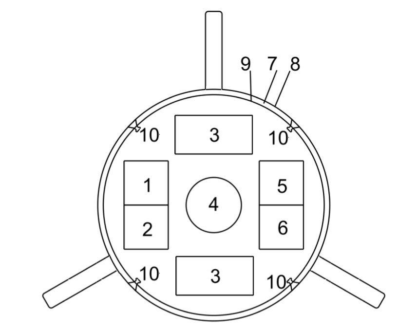
1 - 5.8 GHz digital transceiver module
2 - Antenna coupler
3 - Battery
4 - Antenna rotor / Webcam / Dust wiper
5 - CPU / Memory / GPIO Interface
6 - Voltage regulator / Battery charger
7 - Ceramic fiber shielding
8 - Carbon-kevlar composite shell
9 - ERGAL aluminum case
10 - Differential pressure sensor
PROCESSING UNIT
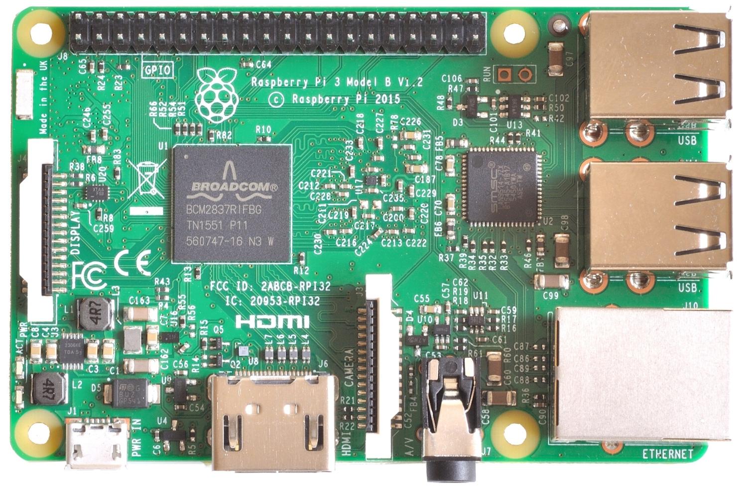
32-bit microcontroller, Real Time Clock (RTC), digital and analog GPIOs, I2C interface, 100Mb/Gb Ethernet shield, A4988 stepper controller board (antenna support and solar panel wiper).
For the job, we have identified the Raspberry Pi, a great low-cost candidate with the needed characteristics.
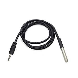
Other than that, we need 4 differential atmospheric pressure transducers, and a 1wire interfaced digital thermometer (like the DS18B20) capable to operate up to -60°C
The opacimeter will be composed by an open plastic tube with an infrared led in one end, and a photodiode on the other. The decrease in the output signal indicates the increase in the dust particles.
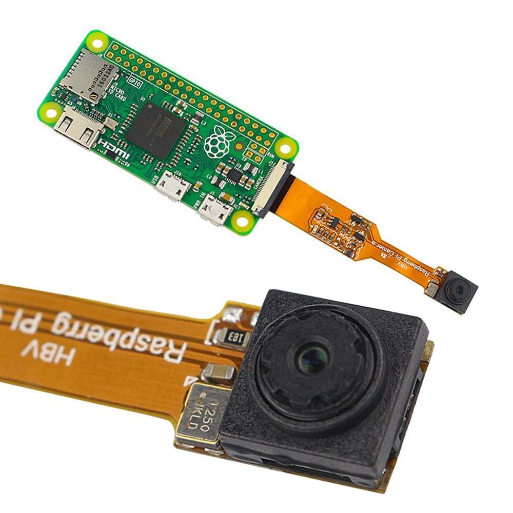
An HD Webcam mounted on the motorized antenna platform.
And a 5,8 GHz digital transceiver. For this purpose, we have identified a commercial piece of hardware commonly used for medium distance terrestrial datalink, like the TP-LINK CPE510.
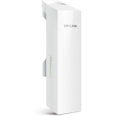
With an adequate high gain directional antenna is possible to transmit data to long distances, even in case of obstacles like depressions and hills. This can be true because unlike on the earth, on Mars the band saturation is almost non-existent.
An interesting solution is the use of a bi-quad or dual bi-quad panel antenna.
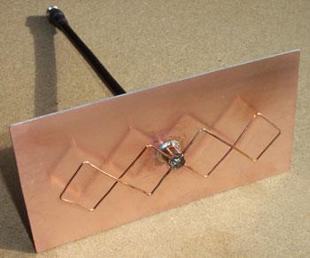
This kind of antenna is characterized by an 8 to 10 dB gain, it has a cardioid irradiation lobe and is compact, sturdy, and easy to produce: ideal for our scope.
DIFFERENTIAL PRESSURE SENSOR
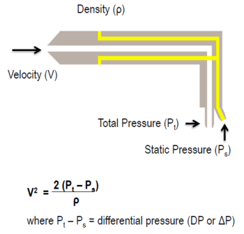
To measure Martian wind speed and direction we have created a solid state sensor, that differs considerably from traditional anemometer mechanical cups, we were inspired by the “Pitot tube” used in the aeronautical sector to measure the relative airspeed, instead of the mill, our sensor uses 4 differential pressure transducers arranged on the circumference of the remote module.
The external inlets are designed to gather the wind that passes by the structure (dynamic pressure) and gets compared with the pressure read in the vertical inlet (static pressure) positioned on the bottom part. Each of the 5 external inlets is equipped with a metallic filter to prevent sand and dust from entering the tube and clogging the sensors.
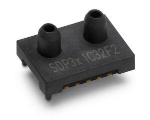
Mars has an atmospherical pressure of just 6,39 mBar or 6,36 hPa, so we need a sensor sensitive enough to read small pressures and pressure differentials, so we have identified the SDP32 as a possible candidate.

The wind direction can be calculated from the relations between the pressure differentials, while the speed is calculated from the vector sum of the positive pressures. Everything is calculated by an algorithm derived from Bernoulli’s law.
This solution brings important advantages because by not having moving parts is really sturdy, and can measure a great range of wind forces.
The measured data can be stored on a memory card for statistical studies and can be sent to the base station on request.
An alert will be sent to the Master station if the measured wind speed is higher than a set threshold.
ENERGY SOURCE AND BATTERIES
Monocrystalline solar panels with a 20W peak power, with high hardness glass able to resist to the Martian abrasive dust.

They will be equipped with an automatic wiper composed of a rotating rubber blade.
(image with solar panels and wiper animation)
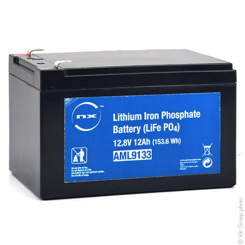
POWER SUBSYSTEM
The energy storage will be made by lithium iron phosphate batteries, that now has the best performance in terms of duration, reliability, and power density.
The total power capacity will be about 12 Ah with a nominal voltage of 12,8V.
The power draw will be monitored by the CPU to grant good energy use, avoiding dangerous voltage drops under the safe limits.
All the power monitoring will be made by an ACS712 module, while for the battery voltage a simple voltage divider will be enough.
When the power generated by the solar panel will be enough, the battery will be charged at a constant current. To avoid the voltage exiting the panel from being lower than the one required for the charging, there will be a switching PULL-UP converter to level the voltages.
The same device will regulate the charging current in order to remain under the safe charging limits.
OPERATING SYSTEM
For standardization, flexibility, and convenience we have decided to use a LINUX based OS like RASPBIAN, that contains all the required utilities, like the network connectivity and the sensors management. The system does not require mass memories like hard drives (that can be easily damaged), but a simple 32/64 GB SD card. The only necessary precaution, because of reliability reasons, is a good cosmic ray shielding made from 20mm thick high-density polyethylene (HDPE) box around the card.
SOFTWARE DEVELOPING LANGUAGE
The software will be developed with Python, because of its great implementation in the Raspberry Pi platform, and is perfectly integrated into the Linux operating system. Python is even portable to other platforms and is free and Open Source.
NETWORK CONNECTION LOGIC
The data exchange between stations will be over TCP/IP (Transfer Control Protocol / Internet Protocol). Every remote module will have its own IP address. The communication can be direct or via nearby modules. The data packets will contain a flag to identify its source and will include an error control marker (parity control), flow control (overflow protection), congestion control (network saturation).
The directive BiQuad antenna will be orientable by using a stepper motor (attached to the webcam and wiper assembly) to optimize the radio signal e make the connection fast and reliable.
PHYSICAL CHARACTERISTICS
Stowed legs dimensions: 500 x 500 x 350 mm
Estimated weight including batteries: 140 N (about 14 Kg.)
Actual weight on Mars: 52.6 N (about 5.26 Kg)
COMPONENTS AVAILABILITY
The project has been designed to use already available components, to avoid high-cost, exotic, or custom materials.
Most of the structural components can be realized with conventional 3D printers.
ESTIMATED COSTS
Development and design: 100 man hours
Software development: 200 man hours
Production and assembly: 50 man hours
Testing and tuning: 100 man hours
Estimated mockup hardware cost: 10.000 Euro
GitHub repository: https://github.com/anonymus00/MSSPAS
The project is OPEN SOURCE and is available to everyone under GNU license (excluding commercial use)
Trieste, October 2018
Eugenio Cosolo, Patrick Boschian, and Gioele De Odorico

SpaceApps is a NASA incubator innovation program.