


The Mars Evolution | Make Sense Out of Mars
The Challenge | Make Sense Out of Mars
Study the Magnetic Field on Mars?
Preparing and reuse the existing technology to create a simple experimental set-up to explore magnetic fields on Mars in 3 Dimensional space
INTRODUCTION
The project is about to study magnetic field on mars surface. Basically, the magnetic field is the region around the magnetic source. It could be represented by magnetic field lines and we assume there will be some interesting result by doing this simple experiment at there.
Most importantly, we should know that magnetic field is a vector quantity. This means there is a direction with the field as well as a field strength. We also should consider the magnetic field surrounding our experimental set-up. Noted from earth surface consist of the north geographic pole is close to the magnetic South Pole while the south geographic pole is close to the magnetic north pole and the direction of magnetic field of a compass is the direction where the north pole of compass needlepoint. Therefore we suggested to bring other set up to see this magnetic behavior in free space.
OBJECTIVES
From the definition, we are motivated to map a three dimensional pattern of the magnetic field in free space at mars.
The main objectives of this:
- were to study the magnitude of the magnetic field with the different axis and
- to observe three dimensional pattern of the magnetic field in mars space.
In this experimental set-up, java program was created to control the movement of DC motor using 2 relay SRD-05VDC-SL-C. Therefore, the DC motor was used to control and position the Hall Effect Sensor, which helps us get the magnitude of the magnetic field by providing steady current. The measurement reading was measured with data acquisition and the three dimensional pattern is mapped by a software named Gnu-plot. The purpose of this lab was to learn about the interaction of magnetic field with Hall Effect sensor. We wanted to know if magnetic field put the Hall Effect theory into action when the position is varied. Since the output voltages of sensor increase when the magnetic field strength increase,.
GENERAL IDEA
This is the part we do our sketching to design the body of the prototype model and also the circuit.
- For the body part, we used CNC Plotter as our close reference on the shape and geometry. At first, we planned to add z-axis where we can change the height between the sensor and the button magnet. So the first sketching is just a raw idea of using CD driver and mounting board as compartment to hold the motor while the base area can move forward or backward, the upper part can move right or left and the vertical one can go up and down. But then we realized we don’t have enough time and resource to make the z-axis so we continue with the same idea but using only x-axis and y-axis.
- For the electronic part, we took the motor positioning control mechanism as reference and also suit it the resources that we have to make the motor move in position, point by point. We did some try and errors to test the motors and choose the configuration to move the DC motors. We took about 3 weeks to come out with the suitable component configuration on circuit. We connect the two DC motors to the circuit and the Arduino Uno using two relays. Three crucial components on our circuit connection are the hall sensor, relays and DC motors.
The hall sensor has three terminals that was connected to; 5V, Vout (A0 and A2) and Gnd of Arduino’s pins while each motor has only two terminals that connect with 5V of Arduino and Normally Open (NO) relay. We used DC motor instead of stepper motor. We used relay with model 5V OUAZ-SS. The relay controls the movement of motors. We used two relays, each relay controls each motors. Motor that controls the x-positioning was connected with pin 8 while the y-positioning connected to 9 pin. We used 6 pin relay but only 4 of them involved in circuit connection. The mechanism of the system is double pole single throw where it accepts 2 inputs, so it able to drive 2 different outputs. One input corresponding to one output. Basically, the number of poles defines how many separate circuits the switch can control while the throw defines how many positions each poles can be connected to.
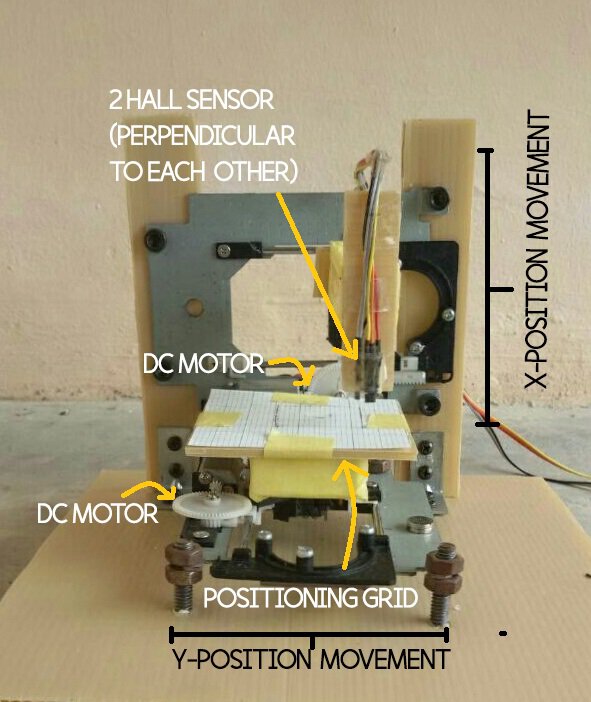
PROTOTYPE MODEL
We basically used the CD driver from unused CPU and used the motor part to control the movement of Hall Sensor along both x and y axis. We used as the holder of the driver as we want to reduce the usage of metal or metal-like materials as it may affect our magnetic field reading. At the same time, we try many ways to connect it in circuit so that we can control it using Arduino. The driver that was set up vertically is for the DC motor that holds the Hall Sensor to move along the points on x-axis on the positioning grid. For another driver that was set up horizontally, it was for the DC motor that holds the Hall Sensor to move along the points on y-axis on the same positioning grid. The Hall Sensor was stick together with cellophane tape and it is perpendicular to each other. The area that we used for the motor movement is about approximately 7cm x 9cm. For programming part, we basically create a simple coding to move the motor first. After few try and error, we manage to obtain the right circuit and coding to make both of the motor move simultaneously in any direction that we set.
PROGRAMMING
Throughout the experiment, we used Java NetBeans for our program instruction. The potential difference in the hall sensor are measured using the Arduino Uno by the execution of the coding constructed in NetBeans.

SpaceApps is a NASA incubator innovation program.